Duct
![]() /
/ /
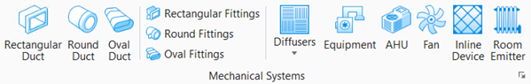
/ Used to place ducts for duct
routing. Ducts of three shapes, viz. Rectangular, Round, and Oval, as well as
Flexible ducts can be placed in your model.
Used to place ducts for duct
routing. Ducts of three shapes, viz. Rectangular, Round, and Oval, as well as
Flexible ducts can be placed in your model.
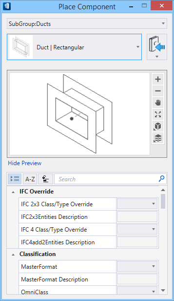
Selecting a fitting from the ribbon panel activates the Place Component settings dialog, where you can manage the schema parameters (DG instance properties). Also, the contextual Placement tab appears on the ribbon, that provides placement settings options for the currently selected fitting.
The generic placement settings, along with the unique set of dimensional and data parameters from the datagroup system provide the core workflow used to accurately position mechanical components within a system.
Component categories
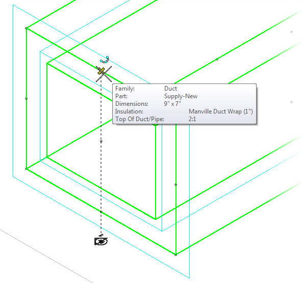
Placing duct employs automatic fitting placement logic that senses the dimensional properties of the duct and orientation in 3D space of the AccuDraw Compass to correctly select combinations of elbows, transitions, takeoffs and coupling components to maintain connectivity throughout the route.
- Round Duct — The primary component in ventilation and air handling systems to transport conditioned air through straight ducts. Rectangular ducts occupy less space and are ideal laying above the ceiling or in a wall cavity.
- Round Duct — Designed to tolerate a faster air flow with less friction, round ducts are economical as they absorbs sound naturally and require less material to transfer the same amount of air.
- Flex Duct — Flexible ducts are convenient for attaching supply air outlets to the rigid ductwork. Short runs minimizes pressure loss.
- Oval Duct — Flat oval duct has been designed for restricted space conditions that cannot accept round spiral duct. Ideal as stacks, especially in homes, allows air to travel vertically within relatively thin walls.
Notable Properties
- Connection End Type – The end conditions of fittings are set to flange, male or female connections with full dimensional control by setting the End Type property. Also, the two ends are independent, and may have different connections. For example, the value fl-2;fe-.13 creates a flange at End1 with size 2, and a female connection at End2 with a clearance of .13.
- Duct Size – Rectangular and flat oval duct have width and depth dimensional properties; W1 & D1. Round duct has a single diameter dimensional property; D1Ø.
- Ridge Distance and Ridge Numbers – Flex duct has two distinct properties controlling its geometry.
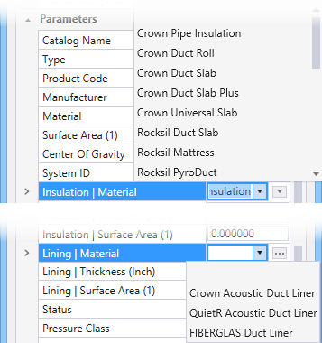
Duct Insulation/Lining

The Lining Thickness adds in the end dimensions and keeps the clear opening of required size. For example, for a 18 x 12 size duct, a 1" lining would add in the width and depth and derive the outside dimension as 20 x 14, used for computing material requirements.

Snap to Insulation and at elevation
Notable Property Options
Set as Default AutoFitting Option – Saves the settings from the active duct, and applies them to duct tool as defaults.
Manufacturer Catalog – Edits the current Catalog having standard properties assigned to the duct, that had set in the Properties via selecting a catalog name.
Notable Placement settings
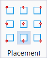
Justification – Nine placement points are available when routing. These options are useful when routing around obstacles, and become powerful design aides when routing with justification.
Single-Line mode – When activated, the routing workflow draws the model in a single line schematic.
Match – Placement options activate matching behaviors that sense and apply to the active component the attributes of existing components.
There are three types of duct. Rectangular, Round and Flat Oval. Round also includes a special type of duct component. Flex duct. The list of ducts available in Duct group is compiled in the Duct Types topic.